Introduction
As with any installation methodology, it helps to run a few test installations before making any changes. This will give you a better feel for the process and boost your confidence that the right choice was made.
For now, the most essential detail regards installing boxes in deep concaves.
As always, if there are any questions, CONTACT us; we are here to help.
Deep Concave Installs
When installing boxes on a board with deep concaves, an extra precaution must be taken to ensure the boxes are installed cleanly.
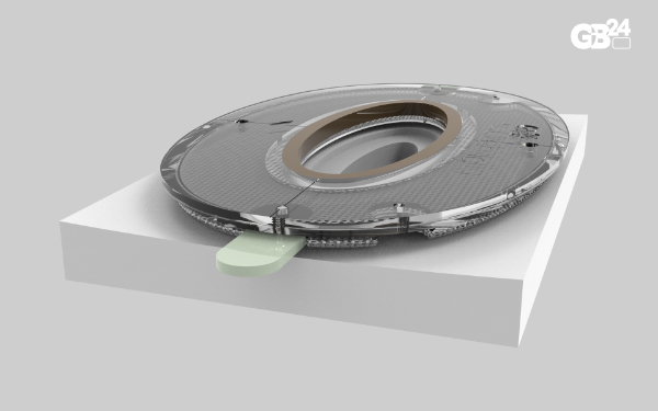
When a router jig is placed over a deep concave area, it can span the curve, as illustrated in the figure below. In this case, using the standard router depth will prevent the box from sitting flush against the bottom of the board.
To compensate, you'll need to increase the depth by the amount of bridging that occurs. Your goal is to position the box below the lowest point of the concave surface. Be aware that the depth gauge by itself won't provide sufficient measurement due to the curvature.
For typical concave surfaces, you'll need approximately 1/32" (0.5 mm) of extra depth.
Always perform a test run to verify adequate depth.
The illustrations below show what things will look like with a standard rout and the compensated-depth version.
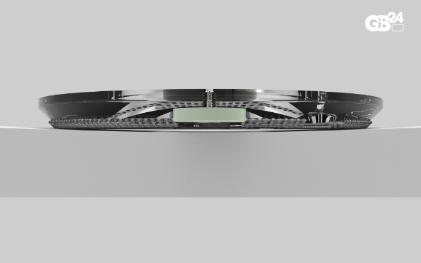
Router jig sitting on a deep concave
End view shows how the router jig spans the concave
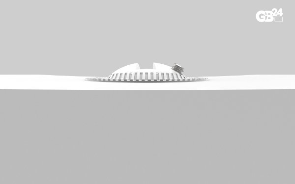
After routing with the standard depth, the box would end up sitting slightly above the lip of the cavity
Normal rout would leave the box sitting above the lip of the cavity
Box set slightly below the lowest lip of the cavity by utilizing a deeper rout
The box needs to be sitting below the lip of the foam at the lowest point
Routing System Details
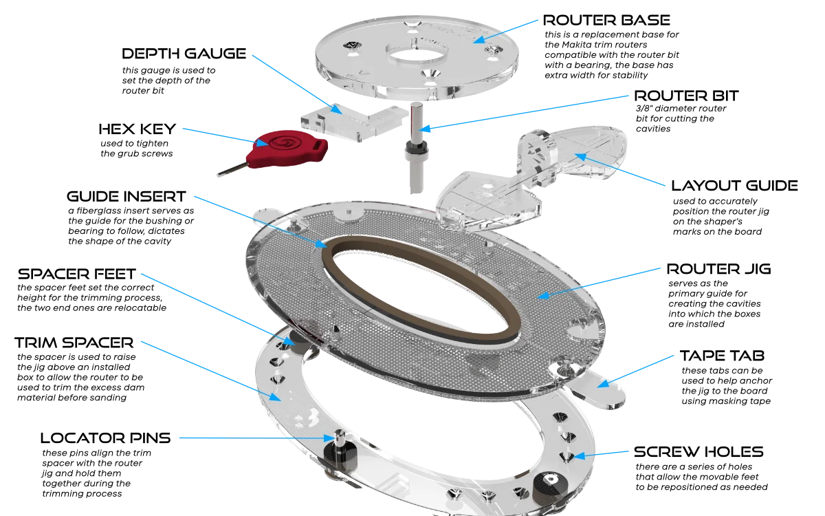
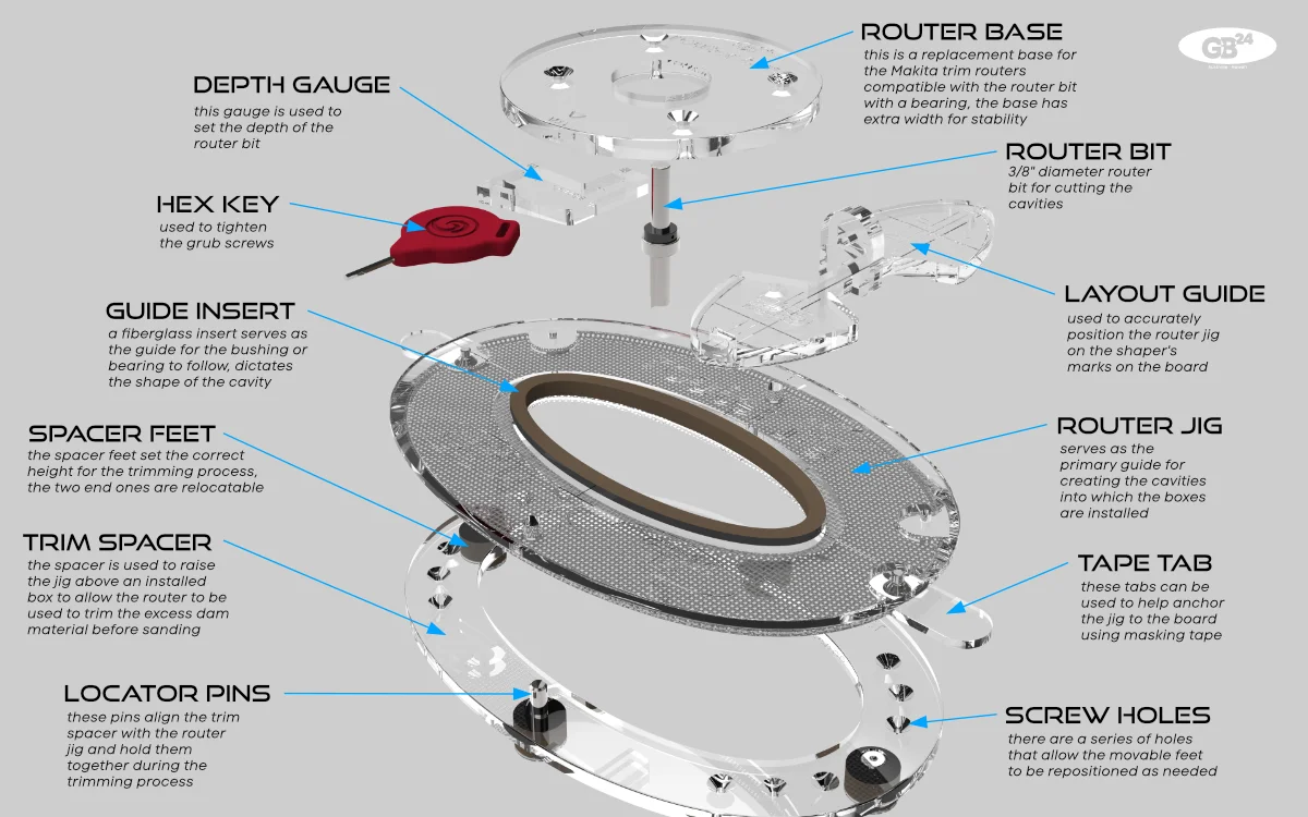
The routing system is fundamentally key to the successful installation of the system. It is essential to understand the role of each of the components.
The illustration details each component of the routing system. The router jig is the central component—everything revolves around it. The jig's primary role is to guide the routing cavities where boxes are installed. A guide insert in the jig, made of phenolic material for strength and wear resistance, serves as the guide. This insert is removable for easy replacement and allows different inserts to be swapped in for future system parts (e.g., a canard box or leash plug).
The jig features optional tape tabs that help attach it to a board during routing. Multiple tab positions facilitate the attachment process. A soft rubber pad on the bottom protects the board, while a beveled edge around the outer perimeter creates a narrower bottom and makes lifting easier. The layout guide, when inserted into the jig insert, helps position the jig on the shaper's marks using engraved layout lines.
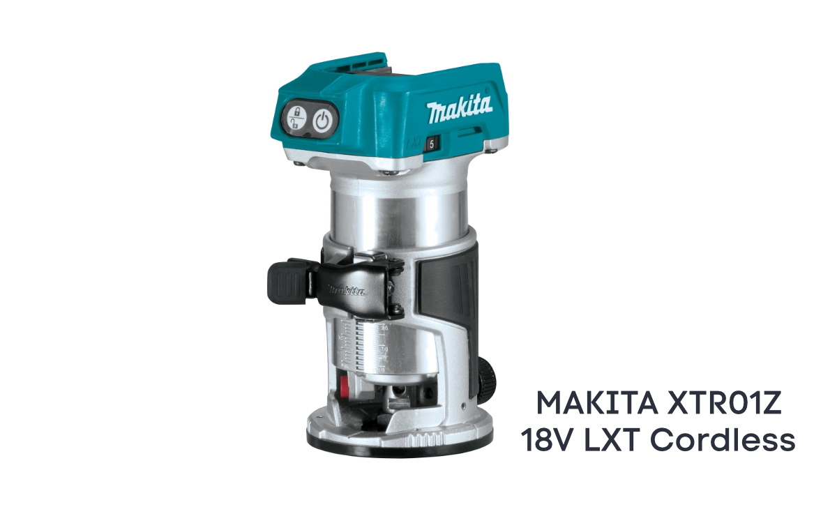
A replacement router base, wider than the standard base, is provided for our recommended trim routers. This increased width enhances stability during the routing process and is compatible with our router bit and bearing.
The router bit must be precisely sized to create the box cavity. The standard router bit is characterized by a 1/4-inch diameter shaft, a 3/8-inch diameter cutter, a 3/4-inch cutter length, and a 1/2-inch diameter bearing.
A depth gauge is provided to help quickly set the initial depth of the router bit in the router. Details on the trim spacer can be found in the next section.
Trim Spacer Details
The trim spacer can save time when sanding down the boxes' dams, but it is crucial to understand how it is utilized.
As part of our routing system, we provide a TRIM SPACER to remove the excess dam material before sanding the board. It is utilized after the board has been hot-coated and before sanding.
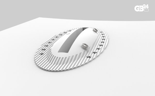
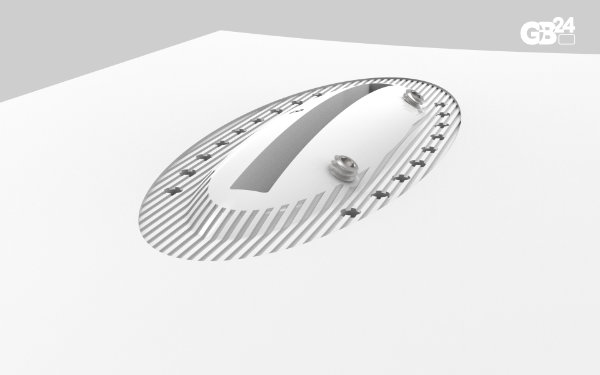
The trim spacer is designed to sit underneath the router jig and raise it by a fixed amount off the bottom of the board. It has two locator pins that align the router jig correctly on top of the spacer. The shapes are symmetrical, but to keep things simple, we ensure that the labels on the jig and spacer are at the top when assembled. The arrow on the jig points towards the rail of the board.
The spacer has four feet, two movable on either end. These movable feet can be relocated to avoid sitting on adjacent boxes or if one is off the rail's edge. The two center feet are fixed and hold the locator pins for the jig.
Each end of the spacer has seven holes into which the feet can be inserted. Each foot has a pin that fits in these holes.
Rubber pads on the bottom of the feet protect the board. Double-sided tape can also be attached to the bottom of these feet to secure the spacer on the board and prevent it from moving during the trimming operation.
Once the jig and spacer have been assembled and placed on the board, the trimming operation can proceed.
WARNING: Before proceeding, ensure the router bit's bottom is above the bottom of the board. If not, the router bit must be adjusted by placing a small spacer washer between the feet and the spacer, enough to raise the jig without changing the router bit height. We provide small rubber spacers that can be used if needed. The bottom of the router bit should be at least 1/16" [1.5mm] above the bottom of the board.
Place the router on top of the jig and make small passes around the dam, removing the excess material. Following the jig edge is unnecessary, as we are not routing that far out. We recommend going slowly and removing small amounts at a time. Ensure the spacer and jig do not move during the process.
WARNING: It is crucial that when the boxes are prepared for installation, the screws are either removed or turned down well into the box, as we do not want to run into them in this trimming process.
NOTE: This process can be skipped if the sander is willing to sand down the dams with a grinder. We recommend using a 40- or 50-grit disc and running the grinder slowly, which helps reduce the plastic's melting. Go slow! It is also advisable to ensure that the screw holes are filled with clay, so that melted plastic does not become lodged in the hole.
BE VERY CAREFUL WHEN USING THIS PROCESS. IF THE HEIGHT OF THE ROUTER BIT IS NOT SET CORRECTLY, IT COULD EASILY DAMAGE THE BOARD. DOUBLE-CHECK EVERYTHING BEFORE PROCEEDING. GO SLOWLY WHEN REMOVING MATERIAL, AS THE ROUTER BIT COULD BIND IN THE PLASTIC.