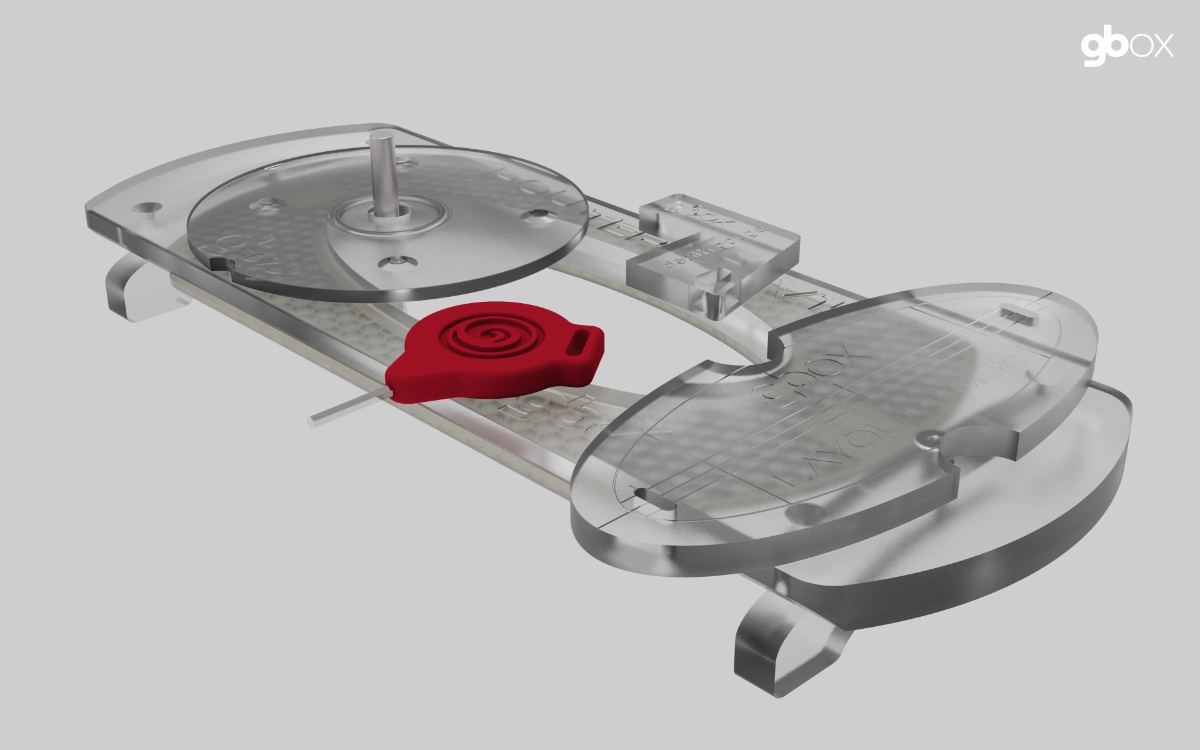
We have reexamined the design of our routing system to enhance manufacturability and functionality. We believe the new design will significantly enhance the original.
Its narrower design facilitates placement in deep double-concaves, while the extended length enhances grip.
The other significant alteration in this redesign is the complete overhaul of the trim spacer, enhancing its usability and positioning. Furthermore, it will be significantly simpler to produce.
For existing users, this will be an optional upgrade, as the current system is unaffected by these improvements. We will be looking into a discounted upgrade path for existing customers once we have the new system finalized.
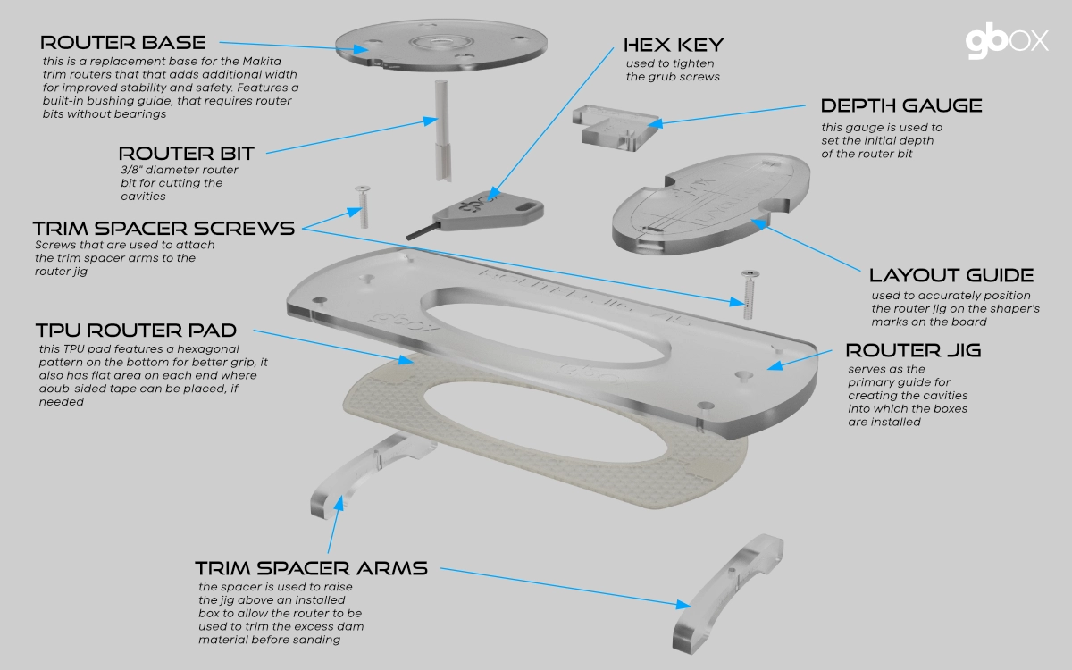
Router Base
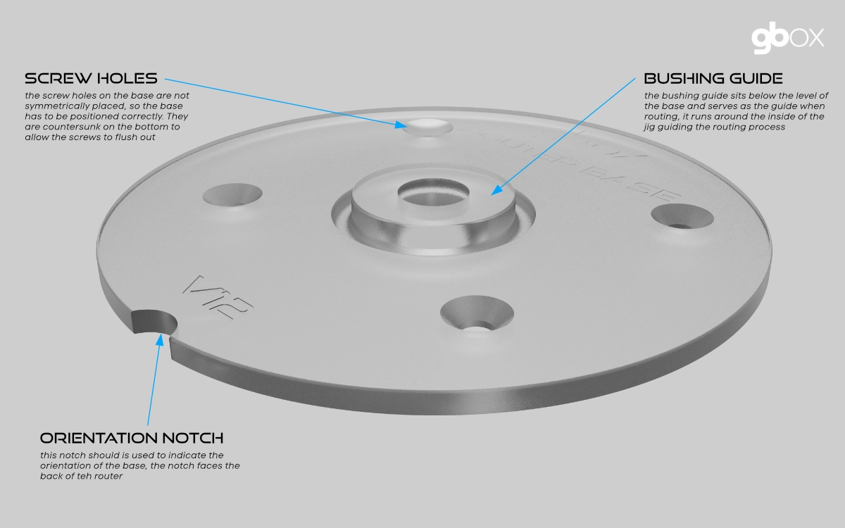
We started with the router base for our changes. Instead of depending on a router bit with an attached bearing to serve as the guiding mechanism, we redesigned the base to incorporate a bushing guide. This guide is not an add-on part; instead, it is machined as an integral part of the base. Moving to a guide eliminated not only the bearing on the router bit but also the need for the phenolic insert that was used in our original jig. The phenolic jig required additional machining and cost.
This change also impacted the jig in that it eliminated the need to machine a cavity for the support flange for the insert. Plus, because of the width of the guide, the router bit is kept far away from the edge of the jig. Minimizing the risks of knicking the jig.
We have two designs for the base to fit either our standard Makita trim routers or a Ryobi trim router.
Router Jig
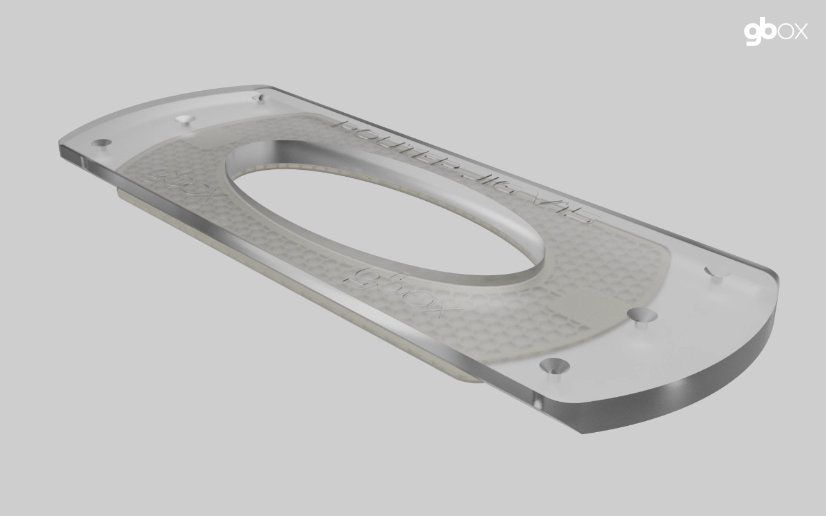
We initiated modifications to the jig to enhance its functionality and facilitate forthcoming improvements.
The initial step involved reducing the width of the jig. The rationale for narrowing it is chiefly that it would enable the jig to fit more effectively in double concaves while also facilitating a more efficient utilization of the material from which the jig is constructed. While narrowing the jig, its length was simultaneously extended. This was executed to facilitate the improved integration of the newly redesigned trim spacer. The extended length facilitates the placement of a hand on the jig during routing.
To further enhance the fit of the jig into concaves, the straight edges on the bottom of the jig are bevelled, effectively making the bottom even narrower.
The jig no longer adds the tape tabs that were found on the original. Instead, we are optionally using double-sided tape to hold the jig in place during the routing process. Some of this tape will be provided as part of the kit.
One other option with this new style of jig is that we can offer to make custom versions of the jig that are even narrower. This might be useful for customers that regularly need to install the boxes in boards with channels. By making the jig narrower, it can better sit down flat in the channel.
Trim Spacer
TThe existing trim spacer was the same shape as the jig and a completely separate part. It had a set of movable feet to facilitate locating it without sitting on adjacent boxes during the trimming process. The shape resulted in a lot of wasted material.
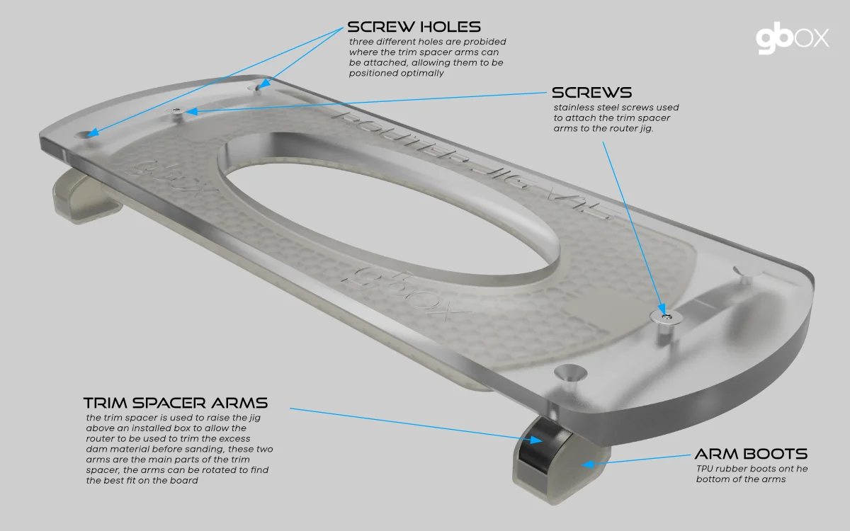
We started with a blank sheet of paper and decided that the trim spacer should be reduced to the smallest possible shape and size while simultaneously improving the functionality. Instead of being a separate part the same size as the jig, it now consists of two narrow arms that attach to the jig with a central pivot point on each end of the jig. With this approach the arms can easily be rotated to keep the feet from resting on any adjacent boxes. Additionally, the feet on the arms can also be moved along the arm to further optimize their placement.
At the arm pivot point a large acrylic washer is placed between the jig and the arm to facilitate rotation but also to allow easier control of the depth of the spacer. Making it easier to control the amount of material removed during the trimming process. Each arm is attached to the jig with a single screw, making them easy to remove. Additional washers are provided to allow for easy depth adjustment. These trim spacer washers have arm extensions that help to stabilize the jig during the routing operation. They also serve to reduce flex in the spacer arms.
The shape and size of the trim spacer arms also make it a lot easier to package them for shipping purposes.
With this new design we can now make four trim spacers out of the same amount of material as a single one of the originals.
Layout Guide
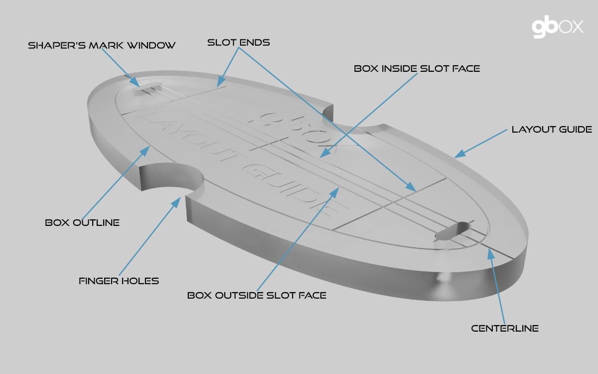
The layout guide is utilized to position the router jig on the shaper's marks. It features a series of lines and markings on the upper surface that represent the outline of the box and the centerline and inside faces of the slot. Additionally, there are two small "windows" that make it easier to align the guide with the marks on the surfboard.
When positioning the guide, the inner line is used to position side boxes, and the centerline is used for center boxes.
The guide is placed inside the inner cavity of the router jig. The jig is then moved around until it is correctly positioned on the marks. Two finger holes in the guide allow it to be lifted out without disturbing the jig.
NOTE: If you are employing double-sided tape to anchor the jig to the board, you will need to slightly elevate the jig while positioning it so as to not have the tape stick to the board.
Features of the guide.
- Centerline This represents the center of the guide and is used to place center boxes.
- Side Lines These represent the inside faces of the box slot. The line closest to the stringer of the board is used to lace side boxes.
- Slot Ends These two lines define where the ends of the slot would be located after installation.
- Shaper's Windows The viewports are used to facilitate positioning the guide on the marks by lining them up in the window using the crosshairs.
- Window Crosshairs These are lines that define the center of the shaper's windows and are used to position the mark accurately within the window.
- Finger Holes There are fingerholes on either side of the guide to facilitate placing and removing the guide within the jig.
- Box Outline An outline of the box is engraved around the perimeter of the guide to help visualize where the box will be placed after installation.
Routing System Guide
This brief guide will detail how the various parts of the system are utilized during the installation process. The description will follow a stepwise flow.
Before starting an install process, the surfboard needs to already have all of the shaper's marks laid out on it, as these will be utilized by the routing system to correctly position the installation. We recommend a 4 1/2" long line between the back and front marks, as these will best line up with the ones on the layout guide.
Before beginning this process on a board, we strongly recommend performing a dummy installation in a scrap of foam. This will serve to familiarize you with the process and boost confidence in the process.
- Place the router jig on the board in the general vicinity of the first box to be routed.
- Insert the layout guide into the center cavity of the router jig. We always orient the guide with the markings facing towards the rail, for consistency.
- Move the jig around on the board until the back mark is lined up with the back markings on the guide. To accomplish this, you will position the mark inside the back shaper's window and line it up with the inside sideline (for a side box) or the centerline (for a center box). The inside sideline represents the inner face of the box slot. NOTE: If you are employing double-sided tape to anchor the jig to the board, you will need to slightly elevate the jig while positioning it so as to not have the tape stick to the board.
- Gently remove the guide from within the jig.
- Ensure that the replacement router base has been attached to the recommended trim router before proceeding with the routing process. The base is attached to the router with the bushing guide facing down. There is also a notch on the edge of the base that should be at the back of the router.
- Set the depth of the router bit utilizing a combination of the depth gauge and the simple depth-check mechanism described in the Install Guide.
- Now that everything is in place, we can proceed with routing the cavity. Start up the router and plunge the bit somewhere in the center of the jig's inner cavity. Move the router till the bushing guide engages with the edge of the jig. Now move the router around the perimeter of the jig in a clockwise direction. Once a full circumference of the jig has been performed, move the router into the inside of the jig and remove all of the remaining foam. Turn off the router but DO NOT remove it from the jig until it has stopped spinning. Once removed, it is a good idea to blow the dust out of the cavity and then run the router around the perimeter one more time to ensure a clean edge. The GBOX box is a tight fit, so a clean edge is crucial.
- Repeat this process for the remaining boxes being installed.
- After all of the boxes have been routed and installed, the routing system will next be utilized to trim down the dam on the boxes. This operation is performed AFTER the board has been hot-coated. The trimming is performed with the trim spacer, which is attached to the router jig. NOTE: This is an optional operation, as the dams could also be sanded down. But there is a lot of material to remove, so the trimming process is the simplest.
- Before being able to perform the trimming operation, the trim spacer arms will need to be attached to the jig. The two arms have numerous positions on the jig where they can be attached. Attach the arms with the 7/8"/22mm screws provided; they are placed below the jig. Before fully tightening the arms, rotate them to ensure that the feet are not sitting on any adjacent boxes.
- With the trim spacer now assembled, position the arms so the whole assembly can still sit flat without one of the feet resting on an adjacent box. We recommend using double-sided tape on the underside of the feet to help anchor the assembly to the board.
- Now that the trim spacer/jig has been placed, check to make sure that the bottom of the router bit is at least 1/16" or more off the face of the bottom of the board. We strongly recommend doing a dummy install in a scrap of foam first and then testing the whole procedure before attempting to perform it on a board. You want to be confident that you are not going to accidentally rout into the board!
- Turn on the router and slowly move it around the perimeter of the inner face of the jig, slowly working your way towards the center as the bit removes the plastic. This does not need to be perfectly smooth, as it will still get sanded down when the board is sanded. The goal here is to remove the bulk of the material but not get it flush with the bottom of the board.
- Repeat this process with the remaining boxes while adjusting the spacer arms to ensure a solid placement on the board.
We also recommend carefully reading the existing installation guide, as it provides a lot more detail on the process. The intent of this short guide is merely to introduce the new system and how it works. Eventually as we move this new routing system to the mainstream, the existing install guide will be updated to incorporate the new system.